Showing posts with label sketches. Show all posts

Wednesday, May 8, 2013

How to Read Schematics; For the Non-Electrician and More Electrical Designs

So last night I started placing the fuse panel and outlets in the galley.  I marked everything and then started fiddling with the fuse panel.  I turned it over and saw this:


And this:

And this:


And this:


I had literally no idea of how to begin connecting my wires to this.  There were only tiny solder points to 'connect' to, or so it seamed to me at first look.  My logical brain said that there is a + and a - side.  The middle must be a ground.  Then I started wondering how in the heck you connect to this when the green circuit board is covering the 'inputs.'  So, I did what I've done in the past, I decided to ask for guidance on the Teardrops and Tiny Travel Trailer Forum.   Within the hour, I had several responses from kind folks who helped me understand the PDF that is on the West Marine website:


 It turns out that the two silver screws are where the 'main' lines to the battery go; slight caveat, I will be adding a buss bar to the negative line as a ground.  The center pole on the fuse panel is actually where the + wire from each circuit's load goes.  After several, very patient, posts, I now understand that this is really pretty simple, but it looked quite complicated to me when I started.  

Once again, I am so grateful to the kindness of others on the Teardrops and Tiny Travel Trailer Forum.  Their combined wisdom helped me through a pickle!

I measured things out last night and it seems that I will be able to put a 'pass through' in the cabin where all the wires will come through.  Thankfully, and by dumb luck, this will all pass below the 'counter top' in the galley.  So, everything will be clean and obstruction free.


You can see from the image above how the main feed from the cabin will enter the cabinet.  I'll run the wires then to the fuse panel, buss bar (ground) and then over to the battery.  I sketched in the 'super simple 120 volt' circuit as well.  This is so that if we have shore power, we can plug in and 'charge up' batteries, or even run appliances directly on the 120 volt current.  I will be putting one 120 volt power outlet in the cabin too.


So far I like the way this is starting to look.  It will be a fairly 'clean' look, while balancing the need to use power when you need it.  The only conflict I can see is that the cooler will not be able to be pulled out when the power ports are being used.  I think that should be fine as generally we will have the cooler out on the ground when in 'camp.'  Having a power port right in that area would allow for a possible 12 volt cooler at some point if we decide that is what we want.  

Here is what the cabinets and electrical receptacles will look like on the inside:


I didn't have a good picture of the inside of the cabin.  You can see, I'll have two large cupboards connected by a small shelving section.  The shelf will be wide enough to fit an iPad for those nights when a campfire isn't possible.

I'm going to use the aluminum shelf to create a 'false' bottom for the cabinets.  By doing this, I'll be able to 'hide' the hole to the power center and disguise the electrical connections for the two 12 volt outlets and the one 120 volt outlet.  The advantage of planning ahead like this is that I am going to provide an access panel to the wiring under the cabinet in case I have to make any 'future' additions or changes.  Also, as you can see from the drawing above, there will be one switch in the center to turn on the 'porch' lights.  

After a lot of research, I decided that it is way too complicated for me to try to have the side marker lights turn on with the porch lights.  It would have been cool, but way too advanced an electrical install for me.   Super Bright LED's was just the place to find four small, cheap LED fixtures.  These four fixtures will be placed, one on each corner of the teardrop, just under the frame.  I can envision how it will look when I turn them on; it's going to be way cool!


 You can see from the images above that they are really tiny, yet very bright.  They also have the added benefit of being able to be a 'replacement' bolt.  That will make the install simple.

The 'porch lights,' which I've shared before, will be really neat when added to this system.


Again, you can see that they are quite small, but very bright.  Again, the ones I'll be using will be red to protect night vision.


I researched the "Super Simple 120 volt Power System" on the TTNT forum and found this excellent, and very simple design:


When combined, the system looks like this:


Or like this:


Mine will be essentially like the one above.  Instead of simply 'terminating' at the three plug input, I will 'daisy chain' the three boxes from the surge protected power cord.


For now, I'm pretty happy with the design.  It will allow us to connect to shore power when we have the opportunity and when we are at home this will prevent me from having to take 'out' the battery in order to charge it.

Tuesday, April 9, 2013

Sketches

I don't get much 'work' done on the teardrop during the week, but that doesn't mean my mind isn't working on problems and ideas for it!

I took some time yesterday to try to measure as many parts of the teardrop as possible.  I'm finding Google Sketch Up to be a real challenge; probably should have started with something a bit simpler at this point, but its fun to experiment.

Here are my rough drafts.
This is the side view.  I drew it so that you could see through the side of the trailer.
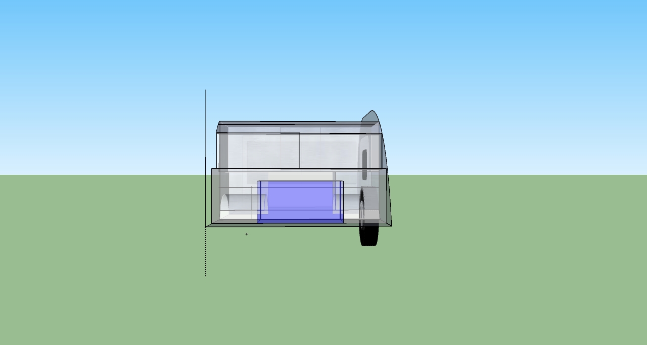
 Rear view; the blue rectangle is the cooler which will be on a pull out slider.
 You can see the cabinetry of the galley and the rough cabinets inside the cabin.
 Side view:  you can see the wheel wells and interior cabinets.
 You can see all the way through the trailer in this image.
 This gives you a sense of the layout in the galley a bit better.

An above view.

I learned a lot about working with Google Sketch Up.  I think these look pretty darn good!  The key was having very specific measurements from the actual teardrop to put into the drawing program.  I learned that you can make the walls transparent.  This allows you to 'see inside' which is very hard to sketch by hand.  I think I'll go back and tweak the cabinetry in the galley and the cabin a bit more in future versions.

 The back view of the galley.
 Possible layouts.
 Estimates for headliner materials.
 Top view above.  Key measurements on the side of the teardrop.
 Battery compartment and power panel possible layout.
 I had no idea how perfectly symmetrical this design was.  It is truly 60.5" wide and 60.5" high.

Key measurements of the galley area.  It's a lot tighter than a lot of other designs.

Sunday, April 7, 2013

All Sealed Up

The cabin is about 90% restored to its original state at this point.  Today I re-caulked every internal joint, re-painted the cabin, and sealed the floor. 


Caulk drying in the seams and joints of the cabin.


Caulk dry and painted.


My three favorite ingredients in sealing the cabin.


I tried to repair all of the trim pieces that thankfully were kept by the previous owner.  The piece you see above goes on the bottom of the hatch and provides rigidity and helps it seal along the 'bumper.'  It was severely warped and misshapen.  I used a piece of the aluminum angle, an aluminum rod, my ball peen hammer, sledge hammer and several chunks of wood to re-form it to its original shape.  At one point I lost my grip on the aluminum piece and my hand slipped.  If I had not been wearing my gloves, I would have ripped an inch or more of my flesh from my hand.  I was very happy to not have that to deal with!

The hatch is looking terrific!

The hatch, and the additional trim pieces that I was able to re-shape.  The piece at the bottom is the 'bumper'  It was in terrible shape.  I love how Rustoleum restores the look of these parts!


This is the inside of the bulkhead.  When the previous owner placed the cabin on the new trailer frame, they did not replace the flooring in this area.  So, this area is the last section of the cabin that I need to repair.  I plan to use a 3/4" x 6" piece of treated wood.  It's a strange shape though, so I'll need to make a template of it and then carefully trim the wood to fit.

You can see in the images above, the area where the cabin was 'cut' to fit onto the new frame.  I don't like the ragged look of this and this is where I will apply some kind of rock guard.  It will act as a 'rock guard' but it will also mask this rough area.  I'm leaning towards using some material in black, just to tie into my color scheme of black and silver.  
I painted the trailer tongue today with Rustoleum.  It looks sharp!  I don't know if I've mentioned a unique element of the trailer tongue.  You can see the triangular piece of metal that is supporting the tongue.  This is a really rare design that is not seen in today's trailers.  Most trailers have a crank jack/wheel that is used when the trailer is off the hitch.  My trailer's design is  much more sturdy and won't 'roll' when in camp.  Jim suggested that I add a jack/wheel, but keep the triangular piece too.
 
 Above you can see my rough sketches for the galley area.  I intend to use Google Sketch Up to try some different layouts for the galley.
  Jim gave me the name of this place; Kendor Marine.  It's only 20 minutes or so from my house and it is essentially a marine surplus store.  They have over 40,000 square feet of stuff.  Jim thought it might be a great idea to take a look there.  I'm wondering if I can find some cabin lights and a fuse panel, etc. there?  I'll have to stop in there sometime soon.  Sounds like a cool place. 

Here is my list of next steps (in no particular order):

1.  Make a template for the mattress; consider how to trim futon.

2.  Make a cardboard template for the bulkhead floor area that needs to be replaced; trim board to fit.

3.   Order windows.

4.   Finish bolting the internal frame to the subfloor.

6.  Experiment with various galley layouts in Google Sketch Up.

7.  Mark out storage box for cabin floor.

8.  Consider laminate covering for the cabin and galley floor.

9.  Draw electrical diagram plan.

10.  Order electrical supplies:  fuse box/power center/voltage meter/shielded red/black wire/corrugated wire channel/easy disconnects, etc.
(Found out that there is a Delta Marine in Winthrop Harbor.  They have my fuse box and additional things in the store.)

These are the steps that are necessary before I can begin to plan for adding insulation, wiring, etc. to the ceiling.  The cabinets in the galley will need to be roughed in as well in order to layout the power center and wiring inside the cabin.  One good thing about putting the power center in the back is that there will be short wiring runs from the power source to the receptacles.